Das verarbeitende Gewerbe in den USA braucht mehr als nur einen“intelligente Kamera„in einer Kiste. Die wahre Energie kommt von der Verbindung. Das ist die Welt der Integrationen von Bildverarbeitungssystemen. Der US-amerikanische Markt für industrielle Bildverarbeitung wächst schnell. Für den Zeitraum 2025 bis 2030 wird eine jährliche Wachstumsrate von über 12% prognostiziert.
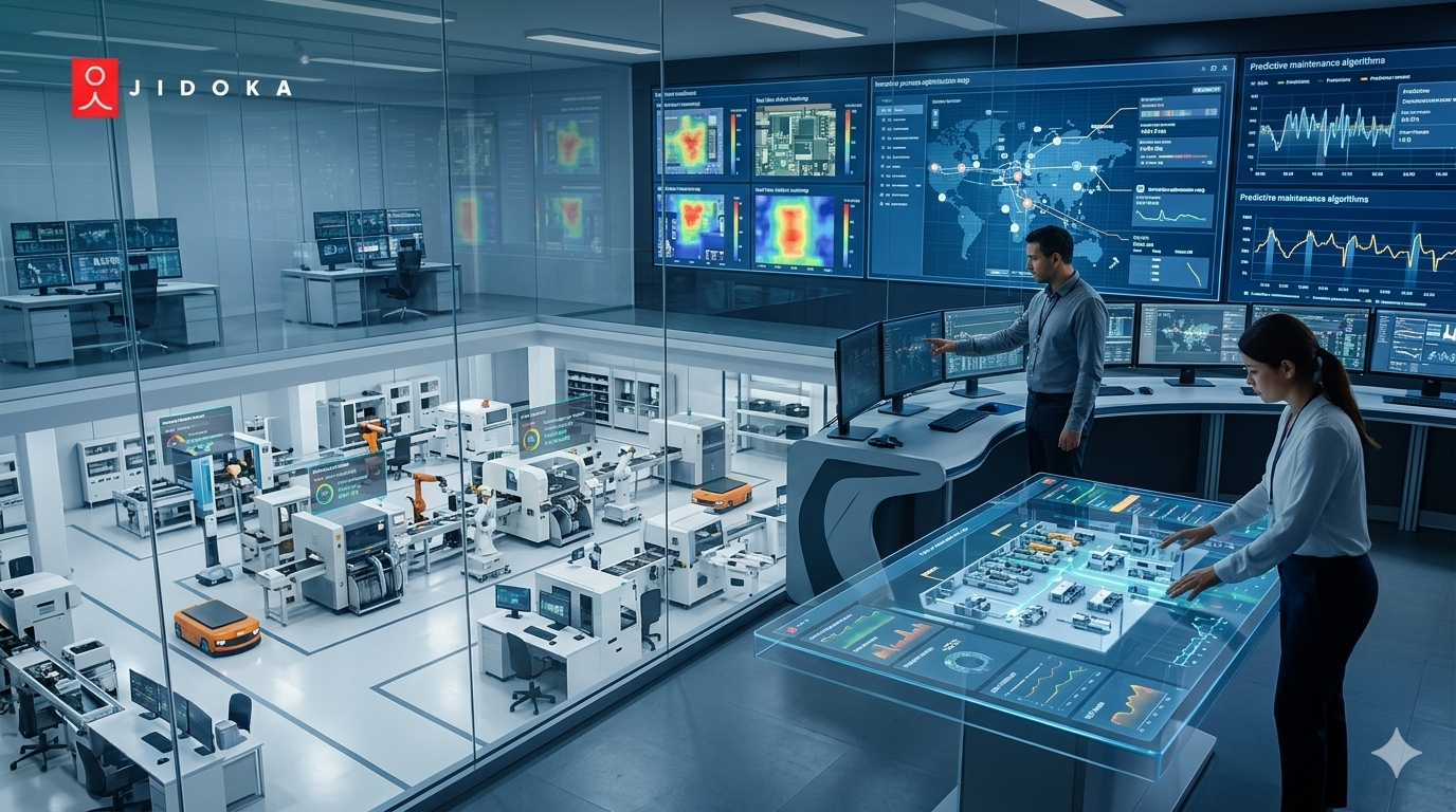
Bei diesem Wachstum geht es nicht nur um bessere Kameras. Es geht darum, KI in die industrielle Bildverarbeitung in die Fabrikhalle zu integrieren. Berichte sind vorbei 60% der Hersteller siehe Integration von robotergestütztem Sehen wie es für eine flexible Fabrikautomatisierung erforderlich ist.
Aber wie bringt man eine Kamera, einen Roboter und eine SPS dazu, dieselbe Sprache zu sprechen?
Dieses Handbuch behandelt die Grundlagen für eine gute Integration von Bildverarbeitungssystemen, von der PLC-Vision-Schnittstelle bis hin zu Gebäudesystemen, die die Linie stoppen, wenn ein Defekt auftritt. Dieses Konzept heißt Jidoka.
Was sind Bildverarbeitungssysteme (und warum machen sie 90% des Projekts aus)?
Der Kauf einer hochauflösenden Kamera ist der einfache Teil. Bei der Integration handelt es sich um eine komplexe und hochwertige Aufgabe, die Kamera zu einem funktionstüchtigen Bestandteil Ihrer Produktionslinie zu machen. Diese Arbeit macht erfolgreiche Integrationen von Bildverarbeitungssystemen aus.
Es ist der Unterschied zwischen einem“coole Tech-Demo„und ein“zuverlässiger Herstellungsprozess.„Eine eigenständige Kamera kann einen Defekt finden, aber ein integriertes System kann in Echtzeit darauf reagieren. Hier bietet ein Integrator für industrielle Bildverarbeitung einen Mehrwert.
Die drei Kernpfeiler der Integration
Echte Bildverarbeitungssystemintegrationen stehen auf drei Säulen.
- Mechanische Integration: Das bedeutet, dass Kamera, Beleuchtung und Optik physisch montiert werden müssen. Es beinhaltet benutzerdefinierte Klammern, Gehäuse mit Schutzart IP67, und stellen Sie sicher, dass das Setup starr ist. Es muss vor Maschinenvibrationen und häufigen Ausfällen von Bildverarbeitungssystemen geschützt sein.
- Elektrische Integration: Es geht darum, die Bildverarbeitungskomponenten mit Strom zu versorgen und die I/O zu verkabeln. Dazu gehören auch das Anschließen von Triggern von Sensoren und das Senden.“Bestehen/Nicht bestanden„Signale an Ablehnungsgatter.
Integration von Daten und Steuerungen: Das ist das Digitale“Handschlag.„Gute Integrationen von Bildverarbeitungssystemen hängen davon ab. Auf diese Weise teilt das Bildverarbeitungssystem das, was es sieht, mit Ihrer Fabrikautomatisierung, wobei häufig eine PLC-Vision-Schnittstelle verwendet wird.
Diese Datenverbindung, die PLC-Vision-Schnittstelle, ist das Gehirn der gesamten Operation. Schauen wir uns das als Nächstes an.
Das „Gehirn“: Das PLC Vision Interface beherrschen
Dein PLC (programmierbare Logiksteuerung) ist der Verkehrspolizist der Produktionslinie. Die PLC-Vision-Schnittstelle ist der Kommunikationskanal, über den das Bildverarbeitungssystem gesteuert und dessen Daten empfangen werden. Ohne eine robuste PLC-Vision-Schnittstelle stoppt Ihre Leitung. Diese Kommunikation ist ein zentraler Bestandteil aller erfolgreichen Integrationen von Bildverarbeitungssystemen.
1. Wählen Sie Ihre Sprache: Allgemeine Kommunikationsprotokolle
Das von Ihnen verwendete Protokoll ist die wichtigste Wahl für Ihre PLC-Vision-Schnittstelle. Dies sind die industriellen Kommunikationsprotokolle, mit denen Ihre Geräte kommunizieren können.
- Ethernet/IP (EIP): Dies ist der vorherrschende Standard in den USA, insbesondere für Rockwell/Allen-Bradley-SPS. Es ist schnell, robust und ermöglicht große Datenpakete.
- PROFINET: Dies ist der Hochgeschwindigkeitsstandard für Siemens-SPS. Sie werden es in vielen in Europa entworfenen Anlagen sehen.
- Modbus TCP: Dies ist ein älteres, einfaches Protokoll. Es funktioniert gut für „Basic“Bestehen/Nicht bestanden„signalisiert, ist aber weniger ideal für komplexe Bildverarbeitungssystemintegrationen.
2. Daten im Vergleich zu I/O: Was senden Sie?
- Diskrete I/O: Das ist die „dumme“ Methode. Eine einfache“Ein/Aus„Signal über ein Kabel. (z. B.“Pin 1 HOCH = bestanden“, „Pin 2 HOCH = Fehlgeschlagen„).
- Datenübermittlung: Das ist die „intelligente“ Methode. Das Bildverarbeitungssystem sendet eine vollständige Datenfolge an die SPS, z. B.:“Teil_OK, X=150,2, Y=301,5, R=90,1„. Diese umfangreichen Daten aus Ihren Bildverarbeitungssystemen sind für die Integration von robotergestützter Bildverarbeitung unerlässlich.
Jetzt, da das „Gehirn“ intelligente Daten sendet, schauen wir uns an, wie der „Muskel“ sie verwendet.
Der „Muskel“: Best Practices für die Integration von robotergestütztem Sehen
Hier wird die Automatisierung flexibel. Die Integration der robotergestützten Bildverarbeitung verleiht Ihrem Roboter „Augen“. Auf diese Weise kann er Teile aus einem beliebigen Behälter auswählen oder ein Bauteil mit einer Präzision im Submillimeterbereich steuern.
Für bildgestützte Robotik ist das Setup alles. Gute Integrationen von Bildverarbeitungssystemen machen hier einen großen Unterschied.
1. Die Entscheidung „Auge in Hand“ oder „Auge in Hand“
Sie haben zwei Hauptoptionen für die Kameraplatzierung in Ihren Bildverarbeitungssystemintegrationen.
A) Auge in Hand: Die Kamera ist am Handgelenk des Roboters montiert.
- Vorteile: Es kann Nahaufnahmen aus verschiedenen Blickwinkeln machen. Es eignet sich hervorragend für die Inspektion eines Teils nach der Roboter hebt es auf.
- Nachteile: Die Kamera ist Vibrationen und potenziellem Kabelverschleiß ausgesetzt. Dies bedeutet auch langsamere Zykluszeiten, da der Roboter anhalten muss, um ein Bild aufzunehmen.
B) Auge in Hand: Die Kamera ist an einer festen Position montiert und blickt auf den Arbeitsbereich des Roboters herab.
- Vorteile: Dieses Setup ist sehr schnell und stabil. Der Roboter kann sich bewegen, um Teil A auszuwählen, während die Kamera Teil B findet.
Nachteile: Der eigene Arm des Roboters kann die Sicht der Kamera blockieren (dies wird Okklusion genannt).
2. Der Albtraum „Hand-Auge“ bei der Kalibrierung
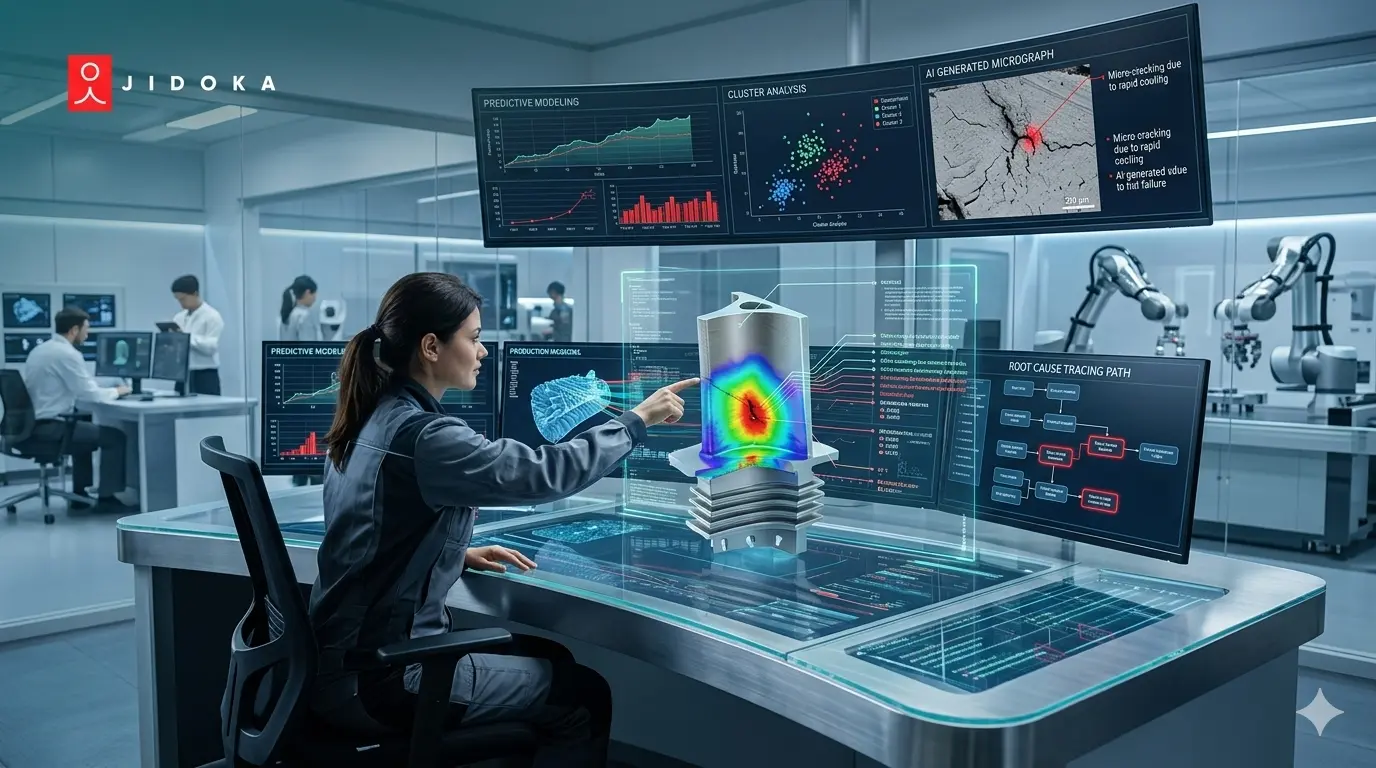
Die größte Herausforderung bei der Integration von Robotik ist die Kalibrierung. An dieser Stelle scheitern viele Integrationen von Bildverarbeitungssystemen. Du musst es der Kamera beibringen 2D-Pixelkoordinaten zu den Robotern 3D-Weltkoordinaten. Eine schlechte Kalibrierung ist einer der häufigsten Ausfälle des Bildverarbeitungssystems und Deshalb „verfehlt“ ein Roboter das Teil um 5 mm.
Hier ist, worum es geht:
- Einen „Handshake“ erstellen: Sie müssen eine präzise mathematische Verbindung zwischen den Pixeln der Kamera herstellen (z. B. „Pixel 800, 600") und der Weltraum des Roboters (z. B. „X, Y, Z“).
- Verwaltung von Daten: Dieser Datenhandshake stützt sich häufig auf die PLC-Vision-Schnittstelle, um den Koordinatenaustausch zu verwalten.
- Das Streben nach Perfektion: Eine einwandfreie Integration von Bildverarbeitungssystemen hängt davon ab, ob diese Kalibrierung perfekt ist.
Dieser Prozess, bei dem Teile gefunden und bearbeitet werden, dient nicht nur der Kommissionierung. Dies ist auch der Schlüssel, um zu verhindern, dass schlechte Teile jemals Ihre Anlage verlassen.
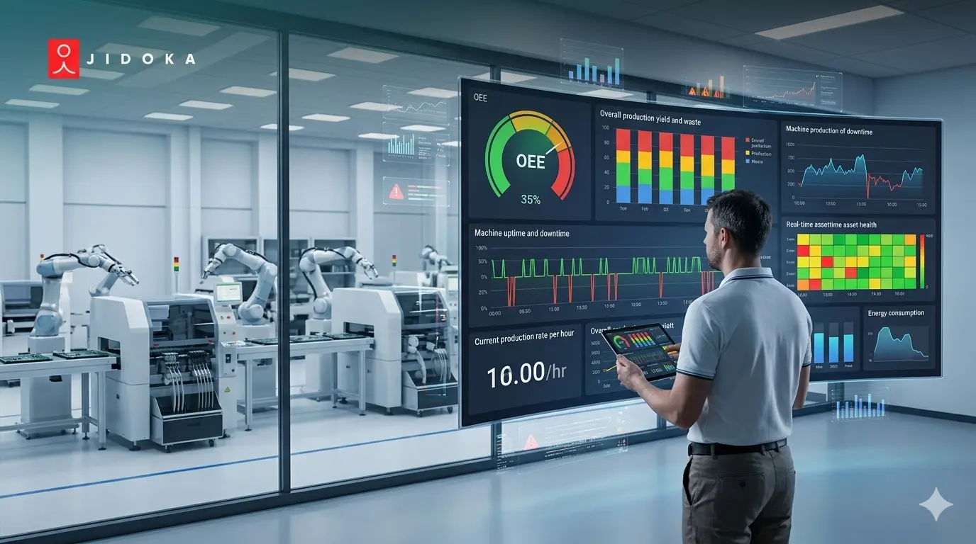
Wie Jidoka helfen kann, Ausfälle zu verhindern
Jidoka Technologies ist ein Unternehmen für industrielle Automatisierung, das autonome KI-Vision-Lösungen anbietet. Ihr Geschäftsmodell basiert auf der Bereitstellung vollständiger, integrierter Systeme (nicht nur Software), die die Herausforderungen der Qualitätskontrolle und Prozessoptimierung lösen.
So funktioniert das:
- Ermitteln: Die Kamera erkennt automatisch einen kritischen Defekt, z. B. ein fehlendes Siegel.
- Stopp: Die PLC-Vision-Schnittstelle ist so programmiert, dass sie die Leitung sofort stoppt, wenn ein schwerwiegendes Problem erkannt wird.
- Warnung: Ein „Andon“ -Lichtturm blinkt rot und ruft einen Operator an.
- Beugen Sie vor: Der Operator startet nicht einfach neu. Sie untersuchen die Ursache (z. B. ist der Verschließer falsch ausgerichtet) und korrigieren den Vorgang.
Wir haben genau diese Logik eingebaut Über 100 erfolgreiche Implementierungen zum 48+ Vertrauenswürdige Kunden weltweit. So hilft Ihnen die Integration von Bildverarbeitungssystemen dabei, Fehler nicht nur zu finden, sondern sie zu verhindern.
Willst du sehen wie Jidoka kann in Ihre Linie eingebaut werden? Lass uns reden.
Fazit: Hör auf, Fehler zu finden, fang an, sie zu verhindern
Bei erfolgreichen Integrationen von Bildverarbeitungssystemen geht es weniger um die Kameramarke als vielmehr um die Qualität der Verbindung. Die eigentliche Arbeit findet im Ingenieurwesen statt.
Ein Integrator für maschinelles Sehen muss komplexe Beleuchtungsprobleme, Vibrationen und schlechte Kalibrierungen für die Integration von Robotik lösen. Die PLC-Vision-Schnittstelle muss schnell und zuverlässig sein.
Sie sind ständig mit unerklärlichen Leitungsstopps konfrontiert. Schlimmer noch, Sie versenden schlechte Teile an Ihre Kunden, was zu Rücksendungen und Vertrauensverlust führt. Ihr teures bildgestütztes Robotiksystem verpasst die Auswahl und verlangsamt so die gesamte Produktionslinie. Am Ende haben Sie ein System, das Fehler findet, aber zu langsam oder unzuverlässig ist, um etwas dagegen zu unternehmen.
Lass uns heute mit Jidoka in Kontakt treten um von der Fehlererkennung zur Fehlerprävention überzugehen.
Häufig gestellte Fragen
1. Was ist der Unterschied zwischen einem Bildverarbeitungssystem und einem Bildsensor?
Ein Vision-Sensor ist eine kompakte Einheit, die oft als Smart-Kamera bezeichnet wird und ein einfaches „Pass/Fail“ -Signal ausgibt. Eine vollständige Integration des Bildverarbeitungssystems ist leistungsfähiger. Es verwendet einen separaten Controller für komplexe KI in der industriellen Bildverarbeitung und sendet umfangreiche Daten wie 3D-Koordinaten über die PLC-Vision-Schnittstelle.
2. Was ist der größte Fehler bei der Integration von Bildverarbeitungssystemen?
Der größte Fehler, der zu häufigen Ausfällen von Bildverarbeitungssystemen führt, ist die unkontrollierte Beleuchtung. Inkonsistentes Licht führt zu Fehleinschätzungen und Fehlausweisungen. Ein professioneller Integrator für industrielle Bildverarbeitung löst dieses Problem, indem er robuste Gehäuse baut und LED-Stroboskopleuchten verwendet, um stabile Bedingungen für die Fabrikautomatisierung zu gewährleisten.
3. Was ist ein „Bildverarbeitungssystemintegrator“ und warum brauche ich einen?
Ein Integrator ist der technische Partner, der den gesamten Umfang der Integration von Bildverarbeitungssystemen abwickelt. Sie benötigen einen, weil sie die Physik (Optik, Beleuchtung) und den Datenaustausch beherrschen und so eine zuverlässige PLC-Vision-Schnittstelle und eine makellose Roboter-Vision-Integration schaffen, die nur für Ihr Produkt gilt.
4. Muss das Bildverarbeitungssystem dieselbe Marke haben wie meine SPS?
Nein, die Marken müssen nicht übereinstimmen. Jedes moderne Bildverarbeitungssystem kann mithilfe industrieller Standardkommunikationsprotokolle wie Ethernet/IP oder PROFINET mit jeder modernen SPS (wie Rockwell oder Siemens) verbunden werden. Kompatibilität ist in das Protokoll integriert.
5. Wofür eignet sich die Integration von robotergestütztem Sehen mit „Auge in Hand“ am besten?
Die Integration von robotergestützter Bildverarbeitung „Auge in Hand“ eignet sich am besten für hochpräzise, flexible Aufgaben in der bildgesteuerten Robotik. Die Kamera wird am Handgelenk des Roboters befestigt, um Nahaufnahmen zu ermöglichen. Auf diese Weise kann der Roboter mehrere Seiten prüfen oder ein Werkzeug mit einer Genauigkeit im Submillimeterbereich in eine komplexe Baugruppe führen.