












HEIGHT & THICKNESS MEASUREMENT

Non-Contact Thickness Measurement
to Catch Wrong-Height Parts

KOMPASS brings non-contact thickness measurement and height inspection into the production run, where a caliper cannot reach. 3D vision builds a height map of each part, compares heights, steps and thickness with your limits and signals the line before a wrong part is assembled.

Discuss Your Height Check

Trusted by manufacturers to improve quality on the line

THE PROBLEM

Height Is the Dimension a Flat Image Cannot See

Many height and thickness checks still happen with a caliper or dial gauge after the part leaves the machine. A standard camera sees length and width, but height needs a different view.

Mid-Run Checks Interrupt the Line

Measuring thickness by hand often means pulling parts or pausing a machine. So the check happens less often than the process needs.

Steps and Stacks Hide in 2D

A missing shim, a raised insert or a stack one layer short can look correct from above. The difference is in height, not outline.

Contact Gauges Mark Soft Parts

Foam, rubber, coated and moulded parts compress or scratch under a gauge. The reading changes with how hard it is pressed.
The Solution

Measure Height and Thickness Without Stopping the Run

Our AI Product Inspection system, KOMPASS™, pairs 3D profile sensors with trained models for non-contact thickness measurement of heights, steps and material on every part. Results reach the line controls with a stored height image.

Turn Each Part Into a Height Map

  • Scan the part with a laser profile sensor or 3D camera as it moves past
  • Measure heights relative to a datum face or reference surface
  • Check step, insert and stack heights in one pass
  • Use two opposed sensors where true material thickness is needed
Every part
Measured mid-run
Height map
Not just an outline
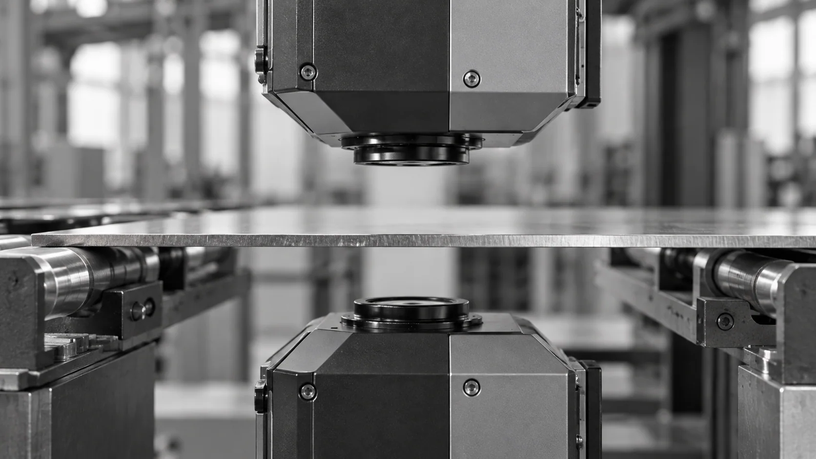
Conceptual illustration of a supported sheet between opposed optical inspection heads.

Separate Real Height Errors From Surface Effects

  • Train on shiny, dark and textured surfaces from your own production
  • Ignore labels, print and colour changes that do not alter height
  • Send pass, fail or review results to the PLC or reject mechanism
  • Log each height reading with its image for trend review
Shape, not shade
Colour does not change the result
Image and value
Evidence for every decision
HOW IT WORKS

From Height Map to Thickness Decision

Non-contact thickness measurement needs depth data, not only a picture. KOMPASS combines 3D capture suited to your surface, measurement from a defined reference and a direct link to the line response.

Highlight #1

Capture Depth on the Moving Part

A laser profile sensor or 3D camera scans the part as it passes. Shiny or dark surfaces are tested early because they affect the sensor choice.

Highlight #2

Measure From the Right Reference

Heights are calculated from a datum face or reference surface defined on your drawing. Two opposed sensors are used where true thickness is required.

Highlight #3

Decide, Reject and Record

Each value is checked against its limit. Failing parts are held or rejected, and every reading is stored with its height image.

Connect With Us

Send us your drawing, the height and thickness limits and a few good and out-of-limit parts. We will assess the 3D sensing and handling the check needs.

Get In Touch

Where Each Height Check Fits

Contact gauges, offline metrology and inline 3D vision each have a role. The difference is how often height gets measured and whether the part is touched.

Measurement need
Manual gauging
CMM & offline systems
KOMPASS AI
Coverage
Sampled parts, often with a pause
Sampled parts, away from the line
Every part, within the validated cycle
Soft or coated parts
Gauge pressure can change the reading
Usually non-contact, offline
Non-contact on the moving part
Steps, inserts and stacks
One feature at a time
Full detail, slowly
Several heights from one scan
First-Time-Right
Relies on catching errors at the next check
Confirms capability after production
Holds wrong-height parts before assembly

Frequently Asked Questions

How does a camera measure height?

Most inline height inspection uses laser triangulation. A laser line is projected across the part and a camera views it from an angle, so the line shifts as the surface rises or falls. Each scan line becomes a profile, and the profiles combine into a height map of the whole part. KOMPASS then measures the features you specify and compares them with their limits. The height image is stored with each result, so a reviewer can see why a part failed.

Is this the same as a profile sensor?

A laser profilometer is the sensor that captures the profile. On its own it outputs height data. KOMPASS adds the inspection layer that turns it into a thickness measurement system: locating the right features on varying parts, applying limits per variant, handling surface effects and connecting the decision to the line. Some applications use a structured-light 3D camera instead, which captures the full area in one shot rather than scanning line by line. The choice between scanning and area capture depends on part size, motion and cycle time.

How is true thickness measured?

Non-contact thickness measurement from one side works only when the part sits on a known surface. Where the underside varies, a dual-sensor setup places one sensor above and one below the part. Thickness is the distance between the two sensors minus the two measured gaps. This suits sheets, gaskets, pads and plates. Calibration with a reference piece of known thickness keeps both sensors aligned over time.

Can it check steps, inserts and stacked parts?

Yes. A step height is measured as the difference between two surfaces in the same scan, so shoulders, raised inserts, pressed-in pins and recessed features can be checked together. Stack height works the same way for piles of washers, laminations or packs, where one missing layer shows up as a height error even when the outline looks complete from above.

What do heights get measured from?

Each height is measured from a reference plane, usually a datum face on the part or the conveyor or fixture surface it rests on. Choosing the right reference matters more than sensor resolution, because a tilted or lifted part shifts every reading. The station can fit the reference from the part itself, which reduces sensitivity to how the part sits on the conveyor. For parts that rock or tilt, a simple guide at the measuring point often removes most of the variation.

Do shiny or dark parts cause problems?

They can. Surface reflectivity affects how much laser light returns to the sensor. Polished metal can create stray reflections, while black rubber returns very little light. Sensor choice, laser colour, exposure and angle are adjusted for your materials during the trial. Because the measurement is based on shape, printed labels and colour changes that do not alter height are ignored.

Why replace a handheld gauge on the line?

A thickness gauge or dial indicator gives a good reading on the parts someone checks. Non-contact thickness measurement on the line checks every part, without pressing on soft or coated material and without stopping the machine. The handheld gauge stays useful for audits and for validating the inline station against a known reference during commissioning. It also confirms that the inline readings agree with the method your audits already trust.

What should we send to plan height checks?

Send the drawing with each height and thickness limit, the materials, the line speed and how parts are presented. Good parts plus known high, low and missing-layer examples help us test the sensors. If outline features also matter, we assess whether 3D vision inspection and a 2D camera should share the station. We then recommend the sensing, reference and reject point for non-contact thickness measurement on your line. A short trial on your own parts settles sensor choice before any hardware is ordered.

CONNECT WITH OUR EXPERTS

Show Us the Height Your Current Check Misses

Share your drawing, height and thickness limits, materials and line speed. We will confirm the 3D sensing your parts need and talk through cost and schedule. A typical KOMPASS rollout runs 6 to 8 weeks.

Discuss Your Height Check
Close video