












LENGTH MEASUREMENT

Length Measurement System
to Catch Out-of-Length Parts Inline

KOMPASS brings a length measurement system onto the production line. Calibrated cameras find both ends of each part, compare the measured length with your drawing tolerance and pass the result to the line controls, so short or long parts are held before assembly or packing.

Discuss Your Length Check

Trusted by manufacturers to improve quality on the line

THE PROBLEM

A Sampled Length Check Speaks for Parts It Never Saw

Cut, formed and extruded parts drift in length as blades wear, material stretches or a stop moves. A length reading taken once a shift describes that one part, not the hundreds made after it.

The Drift Starts Between Checks

A worn cutter or a slipping feed changes length gradually. Parts made between two in-tolerance samples can still fall outside the limit.

Hand Gauging Varies With the Hand

Calipers and tapes depend on where the inspector seats the jaws and how the part is held. Two people can read the same part differently.

Wrong Length Shows Up at Assembly

A short tube, rod or profile is often found when it will not fit the next part. By then a batch may already be cut, packed or shipped.
The Solution

Measure Every Part's Length Before It Moves On

Our AI Product Inspection system, KOMPASS™, works as an inline length measurement system: calibrated vision hardware and trained models locate part ends reliably and measure length against your drawing. The result reaches the line controls and is stored with an image of the part.

Find the True Ends, Even on Imperfect Edges

  • Light the part so both ends stand out from the background and fixture
  • Train on burrs, chamfers, cut faces and normal finish from your own line
  • Measure along the part axis, not just across the image frame
  • Apply separate limits for each part number or variant
Every part
Measured, not sampled
Your drawing
Limits applied per variant
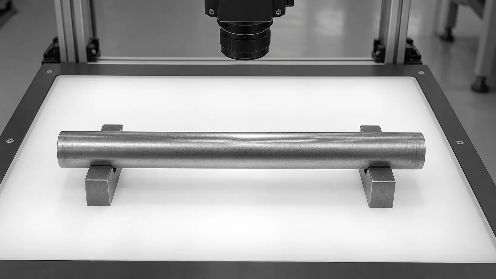
Conceptual illustration of a straight metal rod with both endpoints visible on a backlit inspection stage.

Turn Each Reading Into a Line Decision

  • Send pass, fail or review signals to the PLC or reject mechanism
  • Log every measured length with the part image and a timestamp
  • Show length trends so drift is visible before parts go out of limit
  • Flag a run of near-limit parts for a cutter or stop adjustment
Live trend
Drift visible before rejects
Image and value
Evidence for every reading
HOW IT WORKS

From Calibrated Image to Length Decision

A length measurement system depends on the camera setup as much as on software. KOMPASS combines a fixed, calibrated view, end detection trained on your parts and a direct link to the line response.

Highlight #1

Fix the View and Calibrate It

Mount the camera and lighting for the part's full length, then calibrate pixels to millimetres with a reference target. Long parts may need two cameras or a moving view.

Highlight #2

Locate Both Ends and Measure

The model finds each end face despite burrs, chamfers or a rough cut. Length is calculated along the part axis and checked against the limits for that variant.

Highlight #3

Act on the Result and Keep the Record

In-limit parts continue. Out-of-limit parts are rejected or held, and every reading is stored with its image for traceability and drift review.

Connect With Us

Send us your drawing, the length tolerance and a few in-limit and out-of-limit parts. We will assess the camera, optics and handling the check needs.

Get In Touch

Where Each Length Check Fits

Hand gauges, offline metrology and an inline length measurement system each have a place. The difference is how many parts get measured and how fast a result reaches the line.

Measurement need
Manual gauging
CMM & offline systems
KOMPASS AI
Coverage
Sampled parts, as time allows
Sampled parts, away from the line
Every part, within the station's validated cycle
Repeatability
Depends on the inspector and the gauge
High, in a controlled room
Fixed, calibrated view with the same method each time
Reaction to drift
Found at the next manual check
Found when the lab result returns
Visible in the live length trend
First-Time-Right
Relies on catching drift by chance
Confirms capability after the fact
Holds wrong-length parts before the next operation

Frequently Asked Questions

How does camera-based length checking work?

A length measurement system built on vision uses a fixed camera, controlled lighting and a calibration target to convert pixels into millimetres. Edge detection, supported by a model trained on your parts, finds each end of the part even when the cut is rough. The software measures the distance along the part axis and compares it with the limits for that part number. The result can trigger a reject, a hold or a log entry.

Which parts suit this kind of measurement?

Tubes, rods, profiles, springs, fasteners, cut strips and moulded parts are common candidates. Non-contact length measurement suits soft, hot, coated or delicate parts that a gauge could mark or deform. It also suits lines where parts move too quickly for hand checks. Very long parts may need two cameras, one at each end, or a view that follows the part. Transparent or highly reflective parts need lighting trials first.

Why is backlighting used so often?

Placing the light behind the part creates a backlit silhouette with sharp, high-contrast ends. That makes the end position far less sensitive to surface colour, print or machining marks. Where part height varies or the part cannot sit flat, a collimated backlight with matched optics keeps the edge sharp across the working distance. Front lighting can still work, but it usually needs more training examples to handle reflections and chamfers at the ends.

How should we validate the station before trusting it?

Run a gauge R&R study on the installed station using parts that span your drawing tolerance. Compare the results with your reference gauge and check repeatability across shifts, operators and part positions. As a working rule, measurement uncertainty should use only a small fraction of the tolerance band. If it uses more, change the optics, resolution or part presentation before the station makes automatic accept and reject decisions.

Can it keep up with a moving conveyor?

It can, when exposure, lighting and part spacing are designed for the line. Camera length measurement on a moving conveyor needs a short exposure to avoid blur and a trigger that captures each part in the same position. Processing and rejection also have to fit inside the gap between parts. Feasibility should be confirmed against the full station cycle, not only against how quickly the model returns a result.

What happens to parts that fail the check?

The station signals the configured response, such as an air blow-off, diverter, reject bin or line stop. During the first weeks, out-of-tolerance parts can be held for review instead of scrapped automatically. Every decision is stored with the measured value and the part image. That record helps quality teams confirm that rejects were correct and find the moment a process started to drift toward its limit.

How does this fit our wider quality plan?

Length is often the first dimension worth moving inline because it drifts with tool wear and is simple to verify. A vision measurement system on the line covers every part, while your existing dimensional inspection keeps first-article approval and periodic audits. Many plants add width, diameter or hole checks to the same station later, provided the camera view already contains those features and the optics suit them.

What do you need from us to scope the station for your parts?

Share the drawing with its length limits, the part variants, the line speed and how parts are presented at the proposed station. A small set of good parts plus known short and long parts helps us test the optics. We also ask where a reject can physically happen. With that, we can recommend the camera layout, lighting and handling for your length measurement system and plan the validation.

CONNECT WITH OUR EXPERTS

Show Us the Length Your Current Check Misses

Share your drawing, length tolerance, part variants and line speed. We will confirm what a length measurement system needs at your checkpoint, then walk you through timeline and cost. KOMPASS deployments typically take 6 to 8 weeks.

Discuss Your Length Check
Close video