










SOLDER JOINT INSPECTION

Solder Joint Inspection
to Catch Bad Connections Before Test

KOMPASS brings solder joint inspection to through-hole boards, terminals, connectors and wire terminations. AI models trained on your joints find insufficient solder, bridges, cold joints and excess solder, separating real defects from normal fillet variation before the assembly reaches test.

Discuss Your Solder Check

Trusted by manufacturers to improve quality on the line

THE PROBLEM

One Bad Joint Can Fail the Whole Assembly

An assembly may carry dozens or hundreds of joints. Most are fine, but one bridge or starved joint causes a short, an intermittent fault or a field return.

Manual Checks Miss Subtle Faults

Inspectors working through many joints per board tire quickly. Dull cold joints and fine bridges are the first things missed.

Rule-Based Tools Flag Good Joints

Normal variation in fillet shape and shine looks like a defect to fixed rules, so false calls pile up and slow the line.

Test Catches Some, Not All

Electrical test finds hard shorts and opens, but a weak or cold joint can pass and fail later in vibration or heat.
The Solution

Judge Every Joint the Way an Experienced Inspector Would

Our AI Product Inspection system, KOMPASS™, carries out solder joint inspection with cameras and lighting suited to reflective solder and AI models trained on your joints. Results reach the line controls with an image of every failing joint.

Classify Each Joint by Defect Type

  • Detect insufficient and excess solder, bridges and cold joints
  • Check fillet shape and wetting on through-hole and terminal joints
  • Learn normal variation so good joints are not flagged
  • Inspect from the views each joint type needs
Every joint
Inspected, not sampled
Defect by type
Clear repair instruction
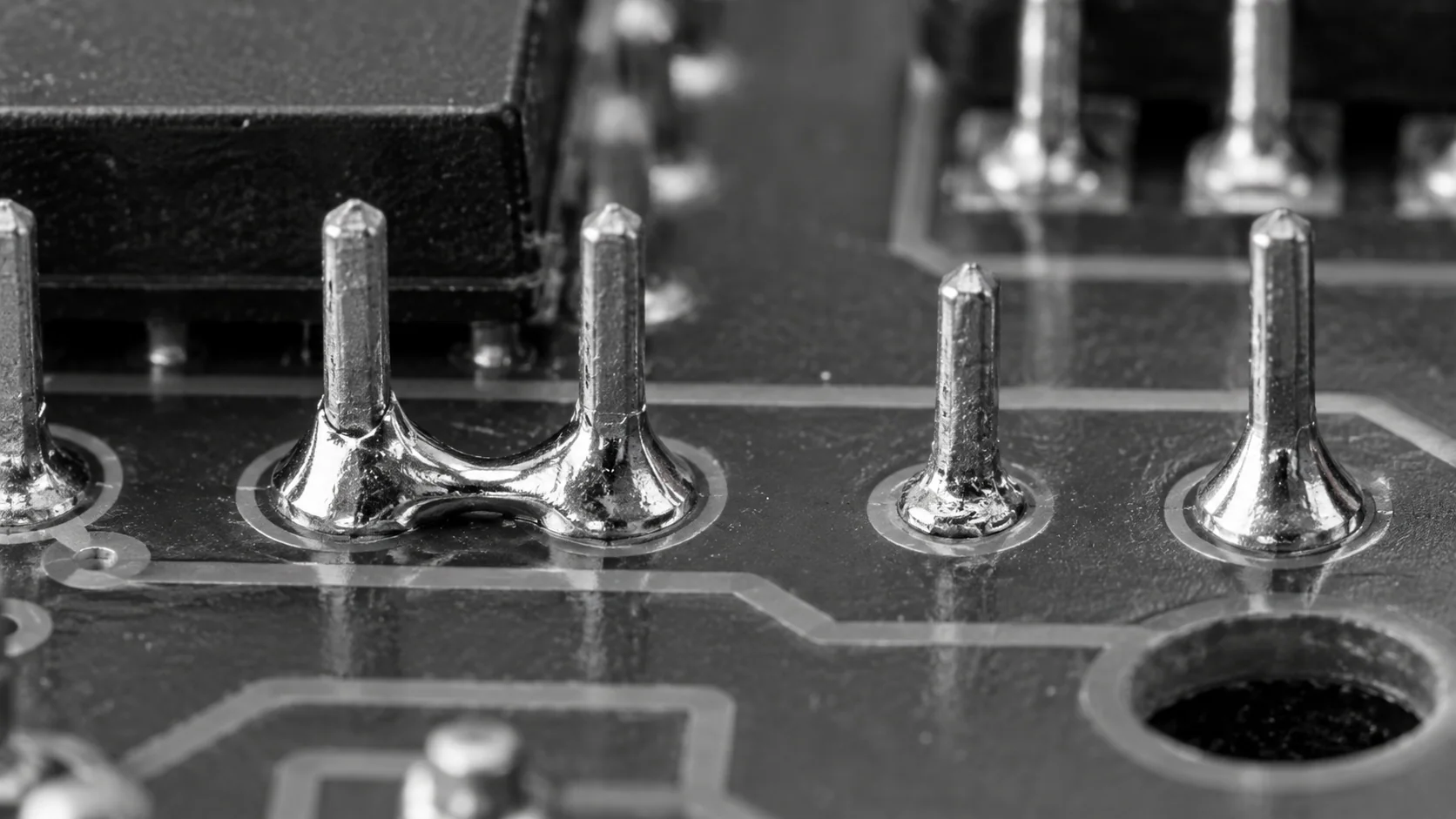
Conceptual illustration of through-hole pins with a solder bridge and varied solder fillets.

Send Repairs to the Right Joint

  • Mark failing joints and their location for rework
  • Trend defects by solder process, nozzle and product
  • Hold failing assemblies before electrical test
  • Store every joint image for traceability
Joint location
Rework goes straight to it
Process trend
Cause visible early
HOW IT WORKS

From Soldered Assembly to Joint Decision

Solder joint inspection depends on lighting and training, because solder is reflective and joints vary in shape. KOMPASS combines both with a direct link to rework and the line.

Highlight #1

Light the Joints From Several Angles

Multi-angle lighting reveals fillet shape and wetting on shiny solder. Joints are captured from the side the defects appear on.

Highlight #2

Classify Every Joint

The model checks each joint and classifies insufficient, excess, bridged and cold joints against your acceptance standard.

Highlight #3

Route to Rework and Record

Failing assemblies go to rework with joint locations marked, and every image is stored for traceability.

Connect With Us

Send us assemblies with typical solder defects and your acceptance standard. We will assess the lighting and views your joints need.

Get In Touch

Where AI Solder Checks Fit

Visual checks, sampling and inline solder joint inspection each play a part. The difference is how consistently subtle surface defects are judged.

Inspection need
Manual visual checks
NDT & destructive sampling
KOMPASS AI
Visible joint defects
Missed as attention fades
Not the main purpose
Classified on every joint
Normal fillet variation
Judged by experience
Not applicable
Learned from your joints
Hidden voids
Not visible
Found by X-ray or sectioning
Not visible, X-ray keeps this role
First-Time-Right
Depends on inspector stamina
Confirms after the fact
Sends faulty joints to rework before test

Frequently Asked Questions

Which defects does automated joint checking find?

Solder joint inspection with KOMPASS finds the defects visible on the joint surface: insufficient solder, excess solder, solder bridges between neighbouring joints, cold or poorly wetted joints, missing joints, solder balls and lifted leads. Each is classified separately, so repair teams know what to fix. Internal voids are not visible to a camera and remain a job for X-ray where required. The result for each joint is stored with its image, so rework and audits start from evidence.

Which kinds of joints can it check?

Through-hole joints after wave soldering or selective soldering are common applications, along with terminal blocks, connector pins, relay and transformer terminals and wire terminations on harnesses. Hot-bar soldering of flex circuits and ribbon cables is another. Each joint type needs its own lighting and views, which are chosen during the trial with your assemblies. Mixed assemblies with several joint types can be checked at one station when the views allow it.

How does it recognise a cold joint?

Cold joints look dull, grainy or lumpy, and the solder does not flow smoothly onto the lead and pad. Those differences are subtle and change with alloy, flux and lighting. Training on your own good and poorly wetted examples teaches the model what matters in your process, which is more reliable than fixed brightness or shape thresholds. Borderline examples are labelled with your inspectors so the model follows their judgement.

Why do rule-based tools raise so many false calls?

Rule-based systems compare joints with fixed limits on shape and brightness. Normal variation in fillet height, shine and lead position breaks those rules, so good joints get flagged. An AI model trained on acceptable variation separates real solder joint defects from harmless differences, which reduces rework queues without letting bad joints through. That keeps rework teams focused on joints that genuinely need attention.

Can it detect bridges between fine-pitch pins?

Yes, where the camera resolution and lighting can resolve the gap between pins. Bridges on fine-pitch connectors and hot-bar joints can be hidden by reflections, so the view is set up to look between pins at a suitable angle. Very fine pitches are tested early in the trial to confirm the imaging can see them. Where a pitch is too fine to resolve, the trial says so clearly before any commitment.

What acceptance standard does it apply?

It applies the standard your quality team uses. Many electronics manufacturers work to IPC-A-610 classes, while harness and terminal makers may use their own criteria. Training examples are labelled against that standard with your inspectors, and validation compares the station's decisions with theirs before automatic decisions are switched on. Different product lines can follow different classes if your customers require it.

Where should the station sit?

Straight after the soldering process is usually best, so defects are caught before electrical test, conformal coating or final assembly. On wave-soldered boards, inspecting the solder side catches bridges and insufficient fill. A second view of the component side helps confirm hole fill on through-hole parts where your standard requires it. Placing the station before test also stops faulty boards consuming test capacity.

What should we send to plan joint checks?

Send assemblies with typical defects, your acceptance standard, drawings or images showing joint locations and the soldering processes you use. Add the cycle time and how rework is organised. With that, we can recommend cameras, lighting and views for solder inspection on your line. Boards from different solder pots or nozzles help show how process changes affect the joints.

CONNECT WITH OUR EXPERTS

Show Us the Solder Defect Your Current Check Misses

Share assemblies with typical defects, your acceptance standard, processes and cycle time. We will scope solder joint inspection before test and lay out timing and cost. Expect roughly 6 to 8 weeks to deploy.

Discuss Your Solder Check
Close video