







WELD MISALIGNMENT & OFFSET DETECTION

Weld Misalignment Detection
to Catch Fit-Up and Offset Errors

KOMPASS checks for weld misalignment on every part: joint edges that do not line up before welding, and welds that land off the joint afterwards. AI vision measures fit-up and weld position against the part and your drawing, then flags the part while the cause is easy to trace.

Discuss Your Weld Check

Trusted by manufacturers to improve quality on the line

THE PROBLEM

Misalignment Weakens a Joint Even When the Weld Looks Good

Weld misalignment starts with fit-up: plates, tubes or brackets that sit offset before the arc strikes. Add a weld that lands a few millimetres off the joint, and one side may never fuse while the bead itself still looks smooth.

Fit-Up Drifts With Fixtures

Worn locators and loose clamps let mating parts sit offset. The weld follows the wrong edge, and the fault repeats on every part.

Variants Multiply the Risk

Different part numbers carry welds in different places. A weld in the right place for one variant is wrong for another.

Offsets Are Hard to Judge by Eye

Inspectors check that welds exist, not whether edges line up or each weld sits exactly where the drawing says.
The Solution

Measure Fit-Up and Weld Position on Every Part

Our AI Product Inspection system, KOMPASS™, detects weld misalignment with vision models trained on your parts, measuring edge alignment before welding and weld position after it. Results reach the line controls with an image of each part.

Measure Joint Alignment and Weld Position

  • Measure edge offset between mating parts before welding
  • Measure each weld's offset along and across the joint
  • Flag welds that are missing, extra or in the wrong place
  • Apply the correct weld layout for each part number
Every weld
Position measured
Per variant
Right layout for each part
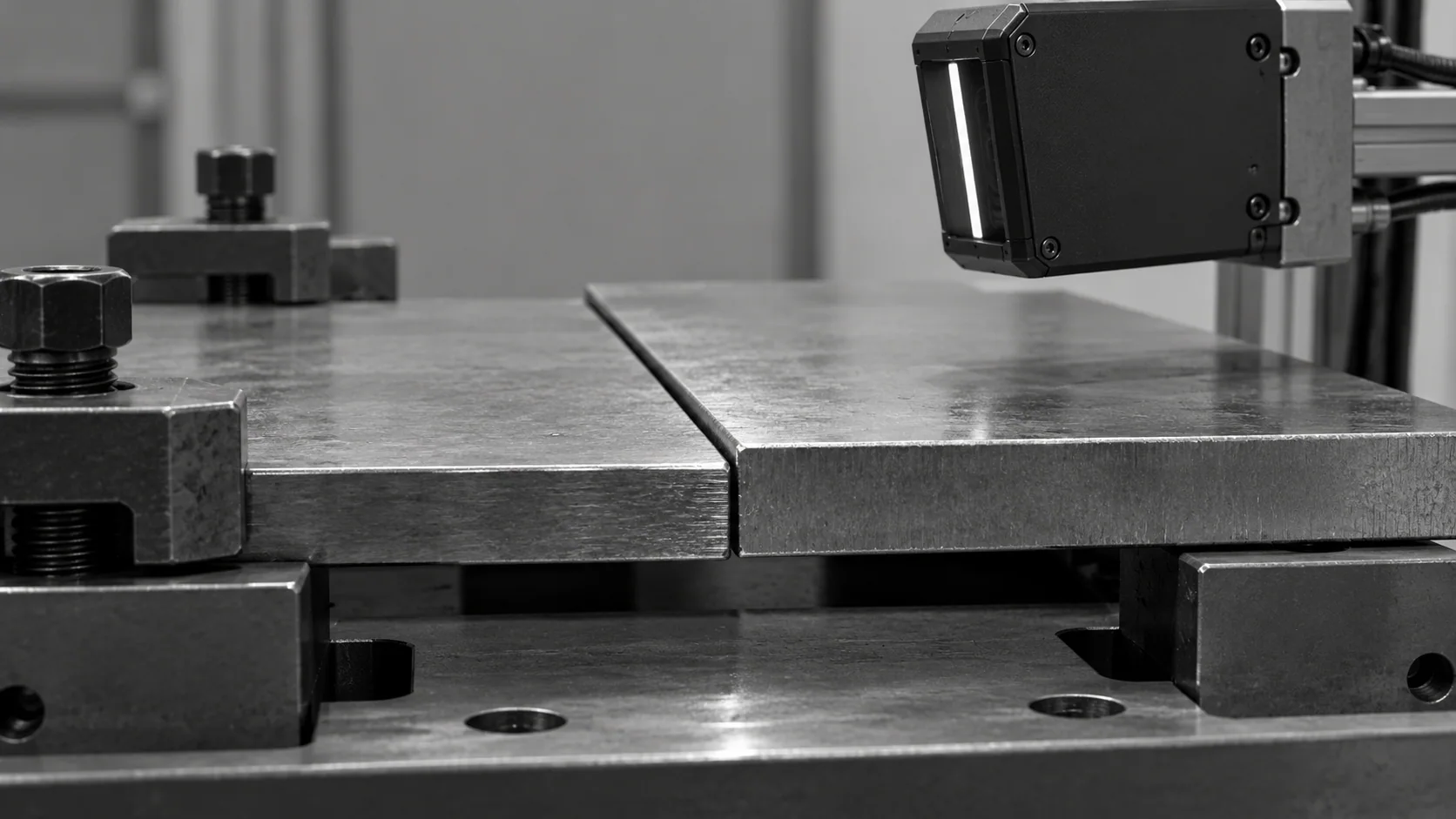
Conceptual illustration of a height mismatch between mating steel-plate edges before welding.
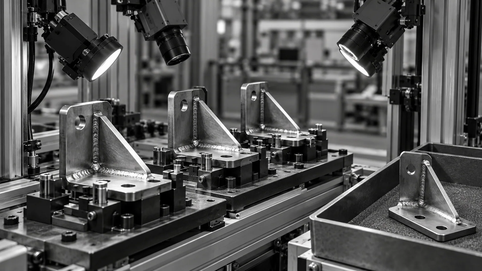
Conceptual illustration of welded brackets in inspection fixtures beside a separate collection tray.

Find the Cause While It Is Still Small

  • Trend weld positions by station, robot and fixture
  • Alert the team when offsets approach a limit
  • Hold parts with welds outside the limit
  • Store every result with its image for review
Live trend
Drift seen before rejects
Per station
Cause easy to trace
HOW IT WORKS

From Welded Part to Position Decision

Weld misalignment checks need a stable view and clear part references. KOMPASS combines both with models trained on your welds and a direct link to the line and the cell.

Highlight #1

Capture Fit-Up and the Finished Weld

Cameras capture each part before welding, after welding or both, with lighting chosen to show edges and welds clearly.

Highlight #2

Measure Offsets Against the Layout

The model finds edges, welds and reference features, then measures each offset against the layout for that variant.

Highlight #3

Hold, Trend and Record

Parts outside the limit are held, offset trends point to the fixture or robot and every result is stored.

Connect With Us

Send us drawings, parts with good and misaligned joints and your limits. We will assess where weld misalignment checks fit in your process.

Get In Touch

Where Inline Position Checks Fit

Visual checks, sampling and inline AI inspection each have a role. The difference is whether weld misalignment is measured on every part.

Inspection need
Manual visual checks
NDT & destructive sampling
KOMPASS AI
Joint fit-up
Checked with gauges on some parts
Seen on sections
Edge offset measured before welding
Weld position
Judged roughly
Measured on sections
Measured against the layout on every part
Gradual drift
Noticed when obvious
Found at the next audit
Trended by station and fixture
First-Time-Right
Relies on careful eyes
Confirms after the fact
Holds misplaced welds before assembly

Frequently Asked Questions

What is weld misalignment?

Weld misalignment is any offset between where the joint or weld should be and where it actually is. It covers joint misalignment, where mating edges sit offset before welding, often called high-low on plate and pipe, and a bead that lands off the joint line. Missing welds and extra welds are reported too, because they come from the same layout check. Each fault is shown on the part image, so the team sees exactly which joint or weld moved.

Why does position matter if the weld looks good?

A well-formed bead that sits off the joint may only fuse one side. That lack of sidewall fusion is hard to see from the surface and can weaken the joint significantly. Checking weld location catches the conditions that cause it, which is cheaper than finding the weakness in destructive testing or in the field. It also gives the welding team evidence to adjust fixtures before strength is affected.

How is position measured?

The station finds each weld and the nearby part features, such as edges, holes or the joint line, then measures the distance between them. Weld offset is compared with the limit for that weld on that variant. Measuring from the part itself, rather than from a fixed point in the image, keeps normal part movement from causing false rejects. The same method works on brackets, frames, tubes and fabricated assemblies.

What causes welds to move?

Fixture wear and loose locators, torch alignment after a collision or nozzle change, a robot path that has drifted and poor joint fit-up are the usual causes. Each leaves a pattern in the data: a fixture problem affects one station, while a torch knock shifts every weld from one robot. Trends make that pattern visible quickly. Knowing the pattern lets maintenance go straight to the right fixture or robot.

Does it work across several products?

Yes. Each of your part variants gets its own weld layout, listing every weld, its zone and its limits. The right map is selected by recipe, barcode or a signal from the cell, so changeovers do not need manual setup. A part welded with the layout of another variant fails immediately. Layouts are updated in one place when an engineering change moves a weld.

Can it detect misaligned plates or joints?

Edge misalignment between plates or tubes before or after welding can be measured when both edges are visible. Where height matters, such as a step between two plates, 3D sensing is added. Checking the joint before welding catches poor fit-up early, while checking after welding confirms the weld followed the joint. Catching fit-up problems before welding also saves wire, gas and cycle time.

Is this the same as seam tracking?

No. Seam tracking guides the torch during welding by following the joint in real time. Position inspection checks the result afterwards on every part. They work well together: inspection data shows when seam tracking or programming needs attention, and it catches errors on cells that have no tracking at all. Many plants use both, with inspection results guiding when to recalibrate tracking.

What do you need from us to scope weld position inspection?

Send drawings showing every weld and its position limits, welded parts with correct and misplaced welds, the variants you run and the cell layout. Add the cycle time and where a held part should go. With that, we can recommend cameras, references and integration for fit-up and position checks on your line. Parts from both ends of a fixture service interval show how much drift the station must track.

CONNECT WITH OUR EXPERTS

Show Us the Weld Position Problem You Want to Stop

Share drawings, weld layouts, variants and cycle time. We will plan weld misalignment checks for fit-up and weld position, with a clear timeline and cost. A KOMPASS project like this typically runs 6 to 8 weeks.

Discuss Your Weld Check
Close video