Manufacturers often miss tiny surface defects. A sheet metal part looks okay to your eye but ruins a complex assembly. You need tools that go beyond old straightedges. Modern flatness measurement uses 3D vision inspection to spot these invisible errors.
This guide explains how flatness inspection technology provides high form accuracy via non-contact measurement. Advanced systems use laser scanning to check surface flatness in seconds.
Jidoka Technologies provides systems that use laser scanning to check surface flatness in seconds. These tools give you the geometric tolerance required for quality sheet metal measurement. Reliable flatness measurement keeps your production lines moving.
What Gets Measured in Flatness Inspection: Eight Critical Parameters Explained
You must understand what your sensors actually see to improve quality. Flatness measurement involves more than checking for a straight line.
Different parts require specific checks to ensure they fit perfectly. Flatness measurement using 3D vision inspection identifies these issues quickly.
1. Planarity Deviation and Peak-to-Valley Measurement
This parameter tracks the distance between the highest and lowest points. Using 3D scanning metrology, you identify the absolute "worst-case" deviation. It confirms your surface planarity meets engineering standards. Reliable flatness measurement depends on these accurate peak-to-valley calculations.
2. Surface Waviness: Periodic Undulations
Waviness refers to repeated ripples across a part, often caused by machine vibration. Advanced flatness inspection technology separates these waves from overall form. This helps you fix production errors. Flatness measurement detects these surface flatness ripples early.
3. Twist and Warp: Three-Dimensional Form Deviations
Twist happens when corners move in opposite directions, creating a warped shape. 3D point cloud analysis detects these complex warps that standard gauges miss. Identifying twist early ensures your sheet metal measurement remains accurate and flatness measurement stays precise.
4. Form Accuracy and Surface Texture
Form accuracy checks if the part matches the CAD design. High-resolution laser scanning also captures optical surface flatness and texture. You get a complete picture of both the micro-scale roughness and the macro-scale flatness measurement in one scan.
Understanding these parameters helps you choose the right hardware for your specific manufacturing needs.
3D Vision Technologies for Flatness Measurement: Structured Light, ToF, and Laser Scanning Compared
Choosing the right hardware depends on your speed and precision needs. Different flatness measurement tools offer varying levels of detail. You need to match the technology to your specific surface flatness requirements to avoid wasting money or missing defects.
1. Structured Light Scanning: High-Precision Production Solution
Structured light projects patterns to capture surface shapes. Using flatness measurement with this method provides 16-17µm accuracy. It is the best flatness inspection technology for complex sheet metal measurement. Jidoka Technologies uses these sensors to ensure high form accuracy on busy lines.
2. Time-of-Flight (ToF) Sensors: Cost-Effective Rapid Verification
ToF sensors measure how long light takes to bounce off a part. This is a fast way to perform flatness measurement for large objects. While it offers lower surface planarity detail, it works well for quick checks. It provides a budget-friendly non-contact measurement option.
3. Laser Triangulation and Baseline References
Laser scanning creates a reference line to find surface dips. This flatness measurement style exceeds the precision of manual gauges. It is a top choice for checking geometric tolerance on machine beds. These systems deliver clear data for optical surface flatness verification.
4. Photogrammetry and Stereo Vision: Flexible, Scalable Approaches
These systems use multiple cameras to build a 3D model. They offer a flexible way to handle flatness measurement on very large assemblies. By using point cloud analysis, they identify deviations in ambient light.
Flatness Measurement Technology Comparison
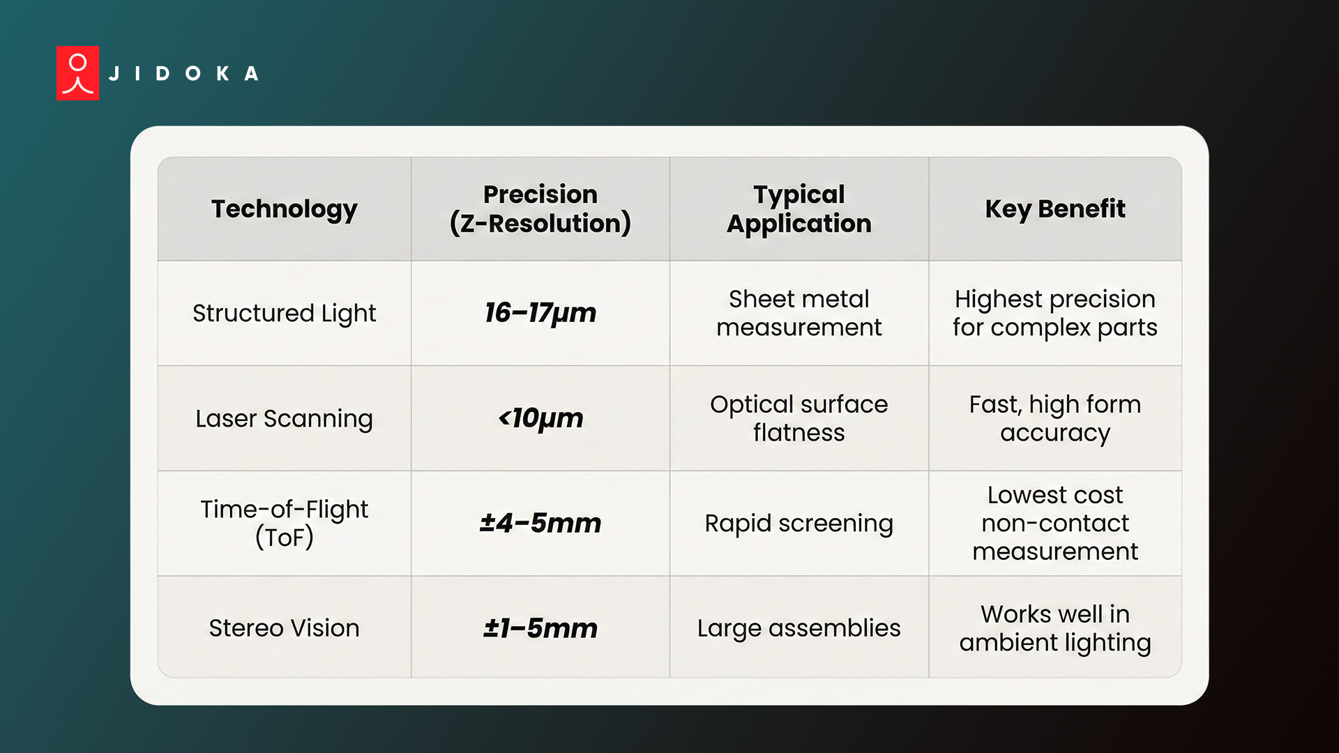
This technology scales easily for different surface flatness inspection tasks. Selecting the right technology ensures your inspection process stays fast and accurate.
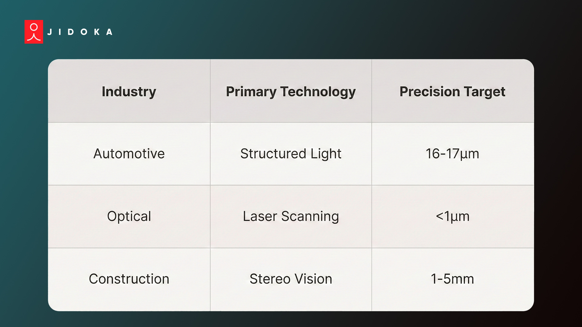
Real-World Flatness Measurement Applications: From Sheet Metal to Aerospace and Optical Surfaces
Industry leaders use flatness measurement to maintain high standards and reduce waste. Applying 3D vision inspection in the field solves real production problems.
These examples show how flatness measurement improves quality across different sectors by providing reliable surface flatness data.
1. Sheet Metal and Automotive Manufacturing
Car makers use flatness measurement for body panels and frames. Sheet metal measurement must be precise to avoid assembly gaps. Using 3D scanning metrology, robots check every part for geometric tolerance in seconds.
This flatness measurement method catches "springback" errors before they reach the welding stage.
2. Optical Surface and Precision Component Inspection
Lenses and mirrors require perfect optical surface flatness to function. Even a tiny bump ruins image quality. Flatness measurement using laser scanning provides the high form accuracy needed for these parts.
Non-contact measurement ensures that delicate surfaces remain scratch-free during the entire flatness measurement process.
3. Concrete Infrastructure and Civil Applications
Engineers now use flatness measurement for large concrete slabs. Instead of manual tools, they use 3D vision inspection to create detailed maps. This flatness measurement approach identifies low spots that could cause drainage issues. It uses point cloud analysis to verify surface planarity across massive construction sites quickly.
Applying these tools correctly helps you avoid costly rework and keeps your customers happy.
How Jidoka’s AI-Powered Vision Solves the Flatness Challenge
Jidoka Technologies builds an AI system that thrives under production pressure. This flatness measurement solution handles 12,000+ parts per minute using 3D vision inspection. You get reliable surface flatness data through two specialized tools:
- KOMPASS: High-accuracy inspector reaching 99.8%+ precision. It reviews frames in under 10ms to ensure form accuracy using laser scanning.
- NAGARE: Assembly analyst that tracks steps via existing cameras. It uses point cloud analysis to cut rework by 35%.
This flatness inspection technology keeps your flatness measurement fast and accurate. Explore how Jidoka’s flatness measurement tools can automate your 3D vision inspection today.
Conclusion
Flatness measurement determines if surfaces meet required planarity for safe assembly. Traditional manual methods or slow CMM sampling often miss subtle warps. These hidden defects lead to structural failures, costly recalls, and lost customer trust. One bad part can stop your entire production line.
Jidoka Technologies offers a better way using 3D vision inspection to automate quality checks. Our system provides real-time flatness measurement to catch errors instantly.
Reach out to Jidoka Technologies to see how flatness measurement precision can help your facility excel.
FAQs
1. What's the difference between flatness, surface roughness, and waviness measurements?
Flatness measurement evaluates overall surface planarity, while roughness checks micro-texture. Waviness identifies periodic ripples. Using 3D vision inspection, you measure all three simultaneously. High-resolution laser scanning allows for advanced point cloud analysis, separating macro-form from micro-scale irregularities to ensure total form accuracy.
2. How does 3D vision flatness measurement compare to traditional CMM measurement?
A CMM uses contact probes and takes minutes per part. Conversely, 3D vision inspection uses non-contact measurement to capture millions of points in seconds. This 3D scanning metrology matches CMM geometric tolerance while providing a complete map of your surface flatness deviations.
3. What accuracy levels are achievable with 3D vision flatness measurement?
Precision varies by sensor type. Structured light achieves 16-17µm for sheet metal measurement, while laser scanning delivers sub-micron optical surface flatness. Choosing the right flatness inspection technology ensures your parts meet every geometric tolerance requirement without wasting time or production resources.
4. How does multi-zone flatness analysis work, and why is it necessary?
Multi-zone analysis applies different tolerances to specific surface areas. One region might need strict optical surface flatness, while others require basic form accuracy. Flatness measurement using 3D vision inspection automates this, ensuring your sheet metal measurement targets critical sealing zones precisely.
5. What production integration challenges exist when implementing 3D vision flatness measurement?
Integrating flatness measurement requires matching sensor speed to your line. 3D vision inspection handles millions of points per second, solving this bottleneck. Non-contact measurement and laser scanning allow for high-speed form accuracy checks, even on complex surfaces, during 24/7 production shifts.